Soviet Union made photo flashes with IFK-120 xenon gas discharge tubes

DO NOT CONNECT the photo flashes described in this section to modern photo cameras.  These old flashes use high voltage synchronization (meant for old mechanical cameras) and will most definitely fry the circuit in the new (digital) cameras.

It should be pointed out that there are some precautions in the manuals below related to the use of such flashes due to the high capacity capacitors and the high voltage used.  A list of safety precautions taken out of the manuals is presented at the end of this web page.

The photo flashes made based on the ИфК-120 (IFK-120) xenon gas discharge light tubes were manufactured with substantial reserve of maximum output power capability and as such are able to deliver a substantial light intensity suitable for more demanding technical and scientific applications beyond photography.  Xenon gas discharge tubes have a wide range of emission lines spanning UV, visible and infrared (see xenon arc lamps), a substantial portion of the radiation being located in the infrared spectrum.   Due to the large number of infrared emission lines a xenon discharge flash is also accompanied with a thermally induced shock wave.  Due to the electrical discharge the flash should also be accompanied by radiation in other spectral bands such as the radio waves.  It is worth noting that there are some later Soviet made photo flashes including models ФЭ-27 (FE-27) and ФЭ-28 (FE-28) which were equipped with weaker light sources compared to what the IFK-120 can deliver.

Table 1
Name in Russian Name in English Manual
СЭФ-3М SEF-3M (SEP-3M) Letter / A4
СЭФ-3 SEF-3 (SEP-3) YouTube at 2:08 min:sec
Фотон Photon Letter / A4
Чайка Chaika (Seagull) Letter / A4
Луч-М1 Luch-M1 (Ray-M1) Letter / A4
Name in Russian / English Maximum flash energy, J Flash duration, s
СЭФ-3М / SEF-3M (SEP-3M) ~36 0.0004 - 0.0006
Фотон / Photon ~36 ~0.0005
Чайка / Chaika (Seagull) 36 0.0005
Луч-М1 / Luch-M1 (Ray-M1) 36, 68, or 104 ~0.0005
Saulute ~36 0.00033

The circuit diagrams listed below are taken from the manuals presented above.   The manuals indicate that the actual electrical circuits used in the photo flashes may contain modifications not listed in the manuals which do not negatively affect the performance of the photo flashes.

СЭФ-3М, SEF-3M (SEP-3M) photo flash schematic diagram and design overview

A schematic diagram (Fig. 1) and photo flash views (Fig. 2) for an old Soviet Union made xenon gras discharge tube based photo flash model: СЭФ-3М, (EN: SEF-3M or SEP-3M)

Figure 1

Figure 2

СЭФ-3М, SEF-3M (SEP-3M)

Fig. 1 and Fig. 2 display the the schematic diagram and different views of the СЭФ-3М, (EN: SEF-3M or SEP-3M) photo flash to illustrate a typical design of an old Soviet Union made xenon gas discharge tube photo flash.  The name of this photo flash probably stands for the "Советская электрическая фотовспышка" (EN: Soviet electrical photoflash).

The operation of the photo flash (see Fig. 1) is as follows (translated from the СЭФ-3М manual with some additions): An accumulative capacitor C2 and an incendiary capacitor C1 are charged trough an AC-to-DC converter.  When the test button S is pressed or the synchronization contact E is closed capacitor C1 is discharged though pulse transformer T which produces a high voltage pulse supplied to the incendiary electrode of the gas discharge tube H2.  The energy stored in accumulative capacitor C2 is released by discharging the capacitor C2 through the gas discharge tube H2 producing a flash of light.

V1, V2 - diode (model Д226Ж)
T - pulse transformer
H1 - neon lamp (model ТН-02-02)
H2 - xenon pulse gas discharge tube (model IFK-120)
R1, R2 - resistor 820 Ohm, 2 W (model МЛТ-2-820 Ом)
R3 - resistor 2.4 MOhm, 0.5 W (model МЛТ-0,5-2,4 МОм)
R4 - resistor 3.3 MOhm, 0.5 W (model МЛТ-0,5-3,3 МОм)
R5 - resistor 680 kOhm, 0.5 W (model МЛТ-0,5-680 кОм)
R6 - resistor 1 MOhm, 0.5 W (model МЛТ-0,5-1 MОm)
C1 - capacitor 0.1 uF, 500 V (model МБМ-500-0,1)
C2 - capacitor 800 uF, 300 V (model Л50-17-300-800)
S - button
X - power cord
E - synchronization cable

Fig. 2 depicts the drawings of the photo flash enclosure where 1 is the test button (to initiate a test flash), 2 is the exposition calculation chart, 3 is the neon lamp view window to indicate when the photoflash is ready for a flash , 4 is the photoflash to camera mounting hardware, 5 is the synchronization cable, and 6 is the power cable.

We acquired 2 flashes of this model.  One of them did not work.  The second flash worked well (without changing the capacitor) and has been used most extensively so far without major issues.

Луч-М1, Luch-M1 (Ray-M1) photo flash schematic diagram and Energy jumper orientations

A schematic diagram with energy jumper orientations for Луч-М1 (EN: Luch-M1 or Ray-M1) photo flash

Figure 3

Луч-М1, Luch-M1 (Ray-M1)

The unique feature of this flash is that it is able to operate at higher electric discharge energies (68 and 104 Joules in addition to the standard 35 Joules) than other Soviet flashes using IFK-120.

The schematic diagram for Luch-M1 photo flash is presented in Fig. 3.   As can be seen the xenon gas discharge tube energy is regulated by changing the orientation of an energy adjustment jumper.

R1 - resistor 820 Ohm, 7.5 W (model ПЭВ-7,5-820 Ом)
R2 - resistor 1.5 кOhm, 7.5 W (model ПЭВ-7,5-1,5 кОm)
R3 - resistor 3 MOhm, 0.25 W (model МЛТ-0,25-3 МОм)
R4 - resistor 68 kOhm, 0.25 W (model МЛТ-0,25-68 kОм)
R5, R6 - resistor 4.7 MOhm, 0.25 W (model МЛТ-0,25-4,7 МОм)
C1 - capacitor 1500 uF, 350 V (model К50-17-350В-1500мкф)
C2 - capacitor 800 uF, 350 V (model К50-17-350В-800мкф)
C3 - capacitor (model МБМ-160В-0,05мкф) 0.05 uF, 160 V
C4 - capacitor (model МБМ-160В-0,1мкф) 0.1 uF, 160 V
В - energy selection jumper
Д - diode (model Д248Б)
Кн - button
Л1 - neon lamp (model ИН-3)
Л2 - xenon pulse gas discharge tube (model IFK-120)
- pulse transformer
Ш1 - power cord
Ш2 - synchronization cable

It should be pointed out that it is recommended to replace the capacitors before plugging it in or using this photo flash.  The one purchased for our tests got overheated, burned a hole in the plastic housing, and almost started a fire during the "training" procedure where you are supposed to keep it connected to the ~220V power supply for some time prior to use.  Online posts indicate issues with this flash after prolonged storage due to the capacitors going bad.

More in-depth information about this and some other old Soviet photo flashes including electrical circuits can be found at this link.

Чайка, Chaika (Seagull) photo flash schematic diagram

A schematic diagram for Чайка (EN: Chaika or Seagull) photo flash

Figure 4

Чайка, Chaika (Seagull)

The unique feature of this photo flash is the ability to power it from a battery in addition to the AC outlet.  However this photo flash caused the breakers to trip when connected to the outlet (through a ~110V to ~220V step up converter).  It is assumed to also be related to the old capacitors in the unit.

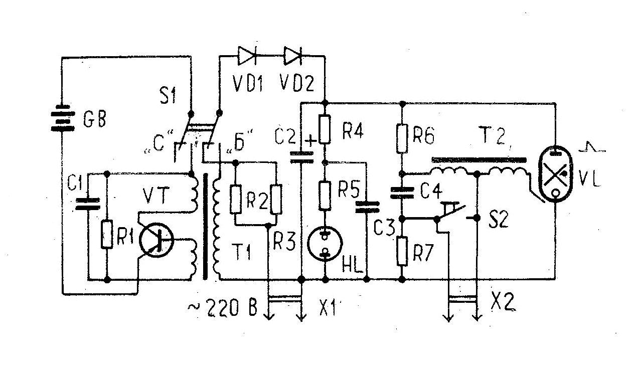
Fig. 4 presents the schematic diagram for the Чайка photo flash.  The electrical components are listed below:

C1 - capacitor 50 uF, 12 V (model К50-12-12В-50мкф)
C2 - capacitor 1000 uF, 300 V (model К50-3ф-300В-1000мкф)
C3 - capacitor (model МБМ-160В-0,05мкф) 0.05 uF, 160 V
C4 - capacitor (model МБМ-160В-0,1мкф) 0.1 uF, 160 V
GB - battery (model 3336Л or 3336У) - Note: These were 4.5V batteries like model "3R12", with 2 batteries used in the flash
HL - neon lamp (model ИН-3)
R1 - resistor 560 Ohm, 1 W (model МЛТ-1-120-560 Ом)
R2, R3 - resistor 1.2 kOhm, 2 W (model МЛТ-2-1,2 кОм)
R4 - resistor 3 MOhm, 0.25 W (model МЛТ-0,25-3 МОм)
R5 - resistor 100 kOhm, 0.25 W (model МЛТ-0,25-100 kОм)
R6, R7 - resistor 4.7 MOhm, 0.5 W (model МЛТ-0,5-4,7 МОм)
S1 - switch (model ТП1-2)
S2 - button
T1 - converter transformer
T2 - pulse autotransformer
VD1, VD2 - diode (model КД105Г)
VL - xenon pulse gas discharge tube (model IFK-120)
VT - transistor (model П4ВЭ)
В - energy selection jumper
Д - diode (model Д248Б)
Кн - button
X1 - power cord
X2 - synchronization plug

Saulute

Three flashes of this model were acquired and all worked without changing the capacitors.

Other models of IFK-120 based photo flashes

Other photo flashes made in the Soviet Union assumed to be using the IFK-120 based on their photos include  СЭФ-3,  СЭФ-2,  Norma FIL-41M,  Norma FIL-46,  Norma FIL-107,  Norma FIL-11,  Электроника Л5-01,  Луч-68,  Луч-70.

Photoflash Capacitor Chargers

It may be necessary for some applications to modify the photo flashes described in this section to enable their operation from batteries.  One way this can be done is by using specially designed Photoflash Capacitor Chargers.  Some of such products are obsolete (i.e. TPS65552A) but may still be available for purchase.

Safety precautions when using IFK-120 based photo flashes

These precautions are taken from the manuals for different flash models.
1) Due to a high capacity capacitor capable of storing a large charge used in the photo flash opening the enclosure and repairs of the photo flash are only allowed 6 hours after the disconnection from a power supply (after the capacitor is completely discharged). Or by triggering a flash (using the test button for example) and leaving the flash disconnected from the power supply for 3 hours.
2) Do not install the photo flash close to the sources of intense heat.
3) Do not connect the flash to a power supply if the flash is removed from the enclosure.
4) Do not use the flash if moisture is present on the surface of the flash.
5) Do not use acetone, gasoline or any other (flammable) solvents to clean up the surface of the flash. To clean the surface of the flash use a dry cloth instead.
6) Allow at least a 20 seconds delay between the successive uses of the flash (the recommended interval varies for different flash models and ranges from 10s to 20s).
7) Do not use the flash outside, in high humidity environment, in buildings with uncovered ground or with floor made of concrete or other conductive material when the flash is connected to the wall power outlet. Autonomous power supplies should be used for such applications.
8) Always disconnect the photo flash from the power supply and discharge the capacitor when changing the batteries.
9) Луч-М1, Luch-M1 (Ray-M1) model only:  Changing the flash energy has to be done after disconnecting the flash from the power supply and discharging the capacitor.
10) Луч-М1, Luch-M1 (Ray-M1) model only:  Do not touch the metallic contacts used to change the energy of the flash with other conductive objects when the flash is powered.
11) Do not pull on the power cord and the switch synchronization cable.

The author of this website does not hold copyright on the manuals for the photo flashes and diagrams taken from these manuals listed on this web page.  Some diagrams include minor additions and translations not present in the originals.

www.bytran.org -|- Page created January 31, 2024;  last edited July 13, 2024
  Email:  bytran@bytran.org
© 2024 Dzianis Pliutau